|
|
"The
drawings were very clear and accurate. The planning and
design were very well thought through."
-Dale Mast, SC Master Builder,
Mast Construction Company
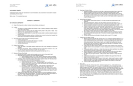
Drawing Checklist
The Drawings and Specifications for your project will compose a
significant and integral part of your Construction Contract with your
Builder, as they will be referenced directly from that contract.
It is imperative that these Drawings are correct and accurately
include any decisions or selections you may have made, in order
to minimize any discrepancies. Should there be any
discrepancy between the Client and Builder during construction,
regarding the inclusion or exclusion of an item, it's
incorporation into the Drawings may decide who bears the cost.
With this in mind, we developed the Drawing
Checklist as a way to determine the types of Drawings and level
of detail based on the client's needs and experience.
Different types of Drawing sheets are noted below, any of which may be used on a particular
project, and their inclusion and level of detail will be noted
in the contract.
The Drawings
|
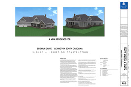 |
Cover Sheet
The Cover Sheet contains
the pertinent information for the project including Project
Overview, General Notes, and other important Information.
A color three dimensional rendering of the finished residence is
also provided. |
|
 |
Specifications
The Specifications include
the identification of materials, fixtures and other selections.
Coordinated with the Drawings, the Specifications provide a
complete overall picture of the project and set the standards
for construction. |
|
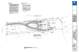 |
Site Plan
Site plans are usually at
1/8" scale and show the property lines, setbacks, structures,
driveways and walkways. It may also include pools,
outbuildings, garden structures and fences in plan, as well as
proposed grading lines. |
|
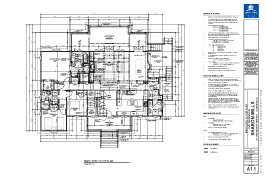 |
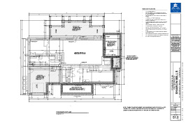
Floor Plans
Detailed plans at 1/4"
scale showing walls, stairs, door & window locations, dimensions
and door and window symbols or sizes. They may also
contain flooring materials, thresholds, ceiling heights and
probable furniture layouts. |
|
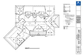 |
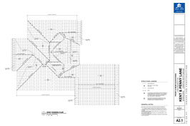
Roof Plan
Roof Plan at 1/4" scale,
coordinated with floor plans and elevations, showing roof
planes, pitches, overhangs, chimneys, gutters & roofing
materials. It may also contain probable locations for
plumbing and mechanical vents. |
|
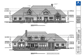 |
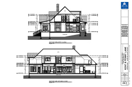
Elevations
Detailed elevations at
1/4" scale, coordinated to floor and roof plans, showing the
front, rear and sides of the home. These typically include
roof lines and slopes, doors and windows, cladding information,
and vertical dimensions to critical floor and roof heights. |
|
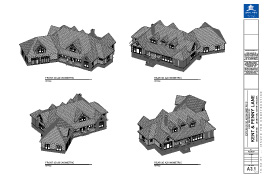 |
3D Axonometric
Exterior and interior
three dimensional overviews are typically line work drawings
that will depict what the finished residence will look like when
construction is complete, enabling everyone to get a clearer
view of the finished home. |
|
 |
Building Sections
Building Sections,
typically at 1/4" scale, are sections or "cutaways" of the
residence. These drawings are used to explain important
information, such as changes in floor, ceiling or roof heights,
and to further clarify the information on the plans. |
|
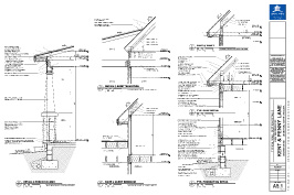 |
Typical Details
Details including typical
wall sections, foundation, eave and other framing details that
are pertinent for the project are included here and are
typically drawn at a larger scale. These drawings may also
include details for custom built-ins and trim profiles. |
|
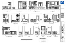 |
Interior Elevations
Interior elevations of
Kitchens and Baths show the arrangement and size of cabinets,
fixtures and appliances in relationship to doors, windows, and
any floor or ceiling height changes. These drawings may
also include tile layouts or other pertinent details. |
|
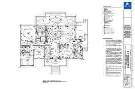 |
Electrical Plans
Electrical Plans at 1/4"
scale are provided as separate drawings, overlaid on the floor
plans. They include the locations of wall outlets,
switches, fixtures, smoke detectors, telephone outlets, computer
outlets and television outlets. |
|
 |
Foundation Plan
The Foundation Plan is
drawn at 1/4" scale showing foundation construction, overall
dimensions, and all openings dimensioned. For concrete
slabs, all plumbing and electrical locations and other slab
penetrations are noted and dimensioned. |
|
 |
Framing Plans
These sheets, when
required, are drawn at 1/4" scale and include floor joist,
ceiling joist and rafter size, spacing and direction. They
also include header and beam sizes, framing details at unique
conditions and structural specifications. |
Learn More...
You can learn more about us, by clicking here:
About Us >>>
Or, you can get more information on green design by clicking here:
Green Design >>>
Or, you can get more information on universal design by clicking here:
Universal Design >>>
Or, you can get more information on 3D Visualization by clicking here:
3D Visualization >>>
|
|